Showing posts with label Arduino. Show all posts

Thursday, October 23, 2014

Tah - Lego block for Internet of Things


TAH Main Board
In this blog post I am going to introduce the Tah platform and talk about some of the applications using it.

Tah is a hardware as well as a software platform.  The hardware has following characteristics
  1. An Arduino with Bluetooth Low Energy (BLE)
  2. Onboard USB (HID device) - emulating a keyboard and a mouse
  3. Great building block (like a LEGO) for your home automation systems using Arduino.

USB HID-Compatible
ATmega32u4 — the microcontroller at the heart of Tah — has onboard USB 2.0 support, that is used to directly program the Tah without having to use a USB-to-Serial converter. Tah can also act as a USB human interface device (HID), which enables you to create your own keyboard, mouse, joystick, or other input devices, all without the need for installing special software on the host computer. If you want to create a new smarter custom keyboard that communicates with your smartphone, you need not look beyond the Tah. It already has sample applications that allow you to control your PC, Mac, Linux, PlayStation and Xbox without ever needing to write any code for those platforms — all you need to do is program your Tah board and make a smartphone app, for which we’ve also provided open source examples for both iOS and Android to get you started.

Bluetooth Beacon

Each Tah board can serve as a Bluetooth beacon which tells your smartphone where exactly it is located based on the beacon’s unique identifier. This is amazing for indoor navigation, contextual notifications, and microlocalization.


Here are some of the interesting applications that can be built using the Tah and its shields.

Infrared Control (IR Transceiver Shield)

IR has been used for near range wireless communication for a long time. We have TVs, music systems, air conditioners and so many other things that have their own remote control  
We have created an IR shield which has a transmitter as well as a receiver on board. With this connected to your Tah, you have a universal remote that can be controlled from your smartphone. Forget keeping a bunch of remotes to control everything in your living room. You could do all of that from a single app on your phone. 

Relays (Relays + Sensors Shield)

Electronics is usually associated with low voltage DC appliances but so much of what we use everyday runs on 110V/220V AC. All our light bulbs, fans and everything else.  
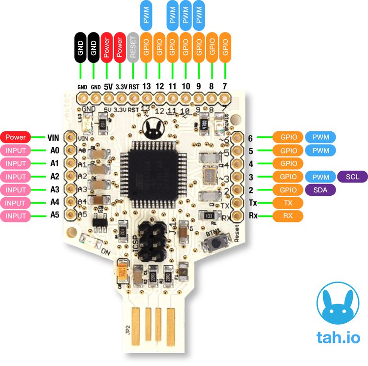
To control these there is a Relay shield that translates signals between DC and AC so to speak. One can use the GPIO pins 2 and 3 from the Tah to control 2 relays. 
Bridge the gap between electronics and electrical with this relay plus sensor shield. It comes with its own app which you can use with some standard sensors such as the depth and temperature sensors among others.
  • Input working voltage: 7V to 12V DC
  • Two Relays rated 5V DC.
  • Load Capacity: 10A/120VAC, 10A/24VDC, 7A/250VAC
  • Relays are connected to Pin number 2 and 3 of Tah
  • Digital Pin Numbers 4 to 13 & Analog Pin Numbers A0 to A5 all are connected to 3 pin standard Grove connector

Arduino

That's why we have the Shield Shield which consists of the Arduino UNO R3 layout which let's you use the already available shields in their projects. This shield makes Tah compatible with all existing Arduino Shields, It means all your Arduino-compatible shields are also compatible with the Tah. (Input working voltage: 7V to 12V DC)

---
By no means is the above list comprehensive. There are many more amazing things that can be built using the Tah.  


Examples on the website. A forum to discuss more about this.

If you would like this device, you can grab them here.

(This is a product of Reavealing Hour Creations who run this blog and the IOT Community)


Friday, August 2, 2013

Arduino with real time web application using web sockets


Purpose of this experiment is to demonstrate real time aspect of the web to pull data from an Arduino.

Arduino can be clubbed together with several sensor to receive data of surroundings and do anything with data. Once you have data with you, imagination is the limit like sending surrounding temperature to Twitter as tweet, check mail when you come close to your computer, turn off volume when an ad comes on TV etc. 

Following POC shows use of Arduino with LDR sensor to plot real time graph of Light around you.

You will need following things for our project : 

  1. Arduino UNO or Freeduino 
  2. LDR or photo-resistor 
  3. 10k ohm resistor (Voltage divider)
  4. Computer 
LDR is basically a simple light sensor that changes the resistance with light. We will measure amount of voltage is on LDR using analog read of Arduino. With Arduino analog read, 5v is highest value read as 1023 and 0v is lowest value read as 0.

Let connect things 


Connect your LDR and resistor as shown in figure., 

Now coding part,
The idea here is to read sensor reading using Arduino and send them to computer for further processing, so we will read sensor data and send it serial port of computer where Arduino is connected. 

filename: LDR.ino

int LDR = 0;

void setup(){
  Serial.begin(9600);
}

void loop(){ 
  int Reading = analogRead(LDR);
  Serial.println(Reading);
  delay(250);
}


Code is pretty self-explanatory. Now the web part here we will use websocket for reading values and plotting real time graph out of read values. We will not discuss websocket and its implementation as this is out of scope of this project (which itself is big topic for discussion).

In order to run the code you need to install Python with following modules 
  1. geventwebsocket.handler 
  2. gevent 
  3. serial 
Python provides module called 'serial' which enables to read and write to serial port of computer.
Here websocket server written in Python, 

filename: LDRreader.py 

from geventwebsocket.handler import WebSocketHandler
from gevent import pywsgi
import gevent
import serial

# PORT used for websocket client
PORT = 8090
import os
import random
def handle(ws):
    """  This is the websocket handler function.  Note that we
    can dispatch based on path in here, too."""
    serial_read = serial.Serial('COM31', 9600)
    if ws.path == '/data':
        for i in xrange(10000):
            signal = serial_read.readline()
            ws.send("0 %s %s\n" % (i, signal))
            print "0 %s %s\n" % (i, signal)
            gevent.sleep(0.1)

def app(environ, start_response):
    if environ['PATH_INFO'] == '/test':
        start_response("200 OK", [('Content-Type', 'text/plain')])
        return ["blah blah"]
    elif environ['PATH_INFO'] in ("/data"):
        handle(environ['wsgi.websocket'])
    else:
        start_response("404 Not Found", [])
        return []


def main():
print "In main, Starting WSGIServer"
server = pywsgi.WSGIServer(('0.0.0.0', PORT), app,
handler_class=WebSocketHandler)
try:
server.serve_forever() 
except:
pass

if __name__ == "__main__":
main()

Now websocket client which will actual receive data and plot it on web browser, you need this library for plotting graph. Download and keep in same directory where LDR.html is present. 

filename: LDR.html

<!DOCTYPE html>
<html>
<head>
<script src="//ajax.googleapis.com/ajax/libs/jquery/1.10.1/jquery.min.js"></script>
<script src="jquery.flot.js"></script>
<script>
var iets = "";
window.onload = function() {
    var data = {};
try {
var s = new WebSocket("ws://localhost:8090/data");
}
catch (e) {
var s = new MozWebSocket("ws://localhost:8090/data");
}
    s.onopen = function() {
        console.log('Websocket Open');
        s.send('hi');
    };
    s.onmessage = function(e) {

      console.log('got ' + e.data);
      var lines = e.data.split('\n');
      for (var i = 0; i < lines.length - 1; i++) {
        var parts = lines[i].split(' ');
        var d = parts[0], x = parseFloat(parts[1]), y = parseFloat(parts[2]);
        if (!(d in data)) data[d] = [];
        data[d].push([x,y]);
      }
      var plots = [];
      for (var d in data) plots.push( { data: data[d].slice(data[d].length - 200) } );
      $.plot( $("#holder"), plots,
              {
                series: {
                  lines: { show: true, fill: true },
                },
                yaxis: { min: 0 },
              } );

      s.send('');
    };
};
</script>
</head>
<body>
<h3>LDR Plot</h3>
<div id="holder" style="width:800px;height:350px"></div>
</body>
</html>

Now start our websocket server using 
# python LDRreader.py  

now go to browser and type http://localhost:8090 and bam !!! 

You will see plotting graph.


Sunday, July 21, 2013

Getting started with the BeagleBone Black

Arduino is the most ubiquitous development platform, period. Anyone who has entered the world of DIY electronics most probably started off with an Arduino. The reasons for this are it's ease, the enormous amount of documentation in the form of wikis, code samples, video tutorials, etc.
But there comes a point when the Arduino just isn't enough for your needs. You need more muscle.

Enter BeagleBone Black.
A 1Ghz, 512MB RAM "mini-computer" with 2 GB of onboard memory.
At $45, its in the competitive price range of the RaspberryPi (35$), pcDuino(59$), etc.

It comes from one of the oldest players in the Embedded Linux worlds, Beagleboard.org. It's their 4th ARM dev board, and the 1st in this price range (previous boards were Beagleboard, Beageboard xM and the Beaglebone white).

Pros as compared to the Pi:
Since the Pi has gained a lot of popularity, it's easier to compare it with that.

  • More processing power(1Ghz as compared to 700Mhz)
  • No need for SD card( has 2 GB of onboard flash, which is more than enough to run your fav Linux distro. Of course it has uSD card slot, just in case you think you need more space)
  • No need for external power supply( directly plugs in to your laptop/PC and runs like the Arduino)
  • Has a LOT more interfaces as compared to the Pi( more GPIOs. Has onboard PWM, ADC too unlike the Pi)
    Full list here http://circuitco.com/support/index.php?title=BeagleBoneBlack
  • Has many many capes available.
    http://circuitco.com/support/index.php?title=BeagleBone_Capes
    Capes are analogous to shields for Arduino.
    It's not always possible to give all kinds of interfaces on the board. So based on your project needs, you can use one of the available capes to add even more functionality.

    You can of course find a lot more comparisons if you ask Google ;) 
Getting started:
Since the BBB rocks Linux on board, you don't really have any restriction on the kind of programming language you choose. 
Any kind of input/output is done by using 

Links to get started:
  1. SRM (System Reference Manual. Read through this once to get familiar with all the features and interfaces.)
  2. Wiki
  3. Mailing list (this should be your first stop for any issues once you get your Black. It's very active and very helpful. Remember to search previous posts before posting your doubt, someone might have had the same doubt)
  4. IRC - #beagle on Freenode
  5. Derek Molloy's blogs ( has some really cool tutorials, videos, etc to get started)
  6. Userspace Arduino project
Get it:
Some of the Indian shops which will ship you a Black are
  1. http://tenettech.com/product/2912/beaglebone-blackhttp://tenettech.com/product/2912/beaglebone-black
  2. http://shop.sumeetinstruments.com/index.php?route=product/product&keyword=beaglebone+black&category_id=0&product_id=965
  3. http://www.crazypi.com/index.php?route=product/product&product_id=79&search=beagle

    Note: these guys don't really have permanent links to their products. So if above links don't work, try searching for them from the Homepage.
DigiKey, Adafruit, element14, etc are the official distributors for the BBB. More info about them here http://beagleboard.org/Products

Saturday, July 13, 2013

Open Source Home Automation Project using Arduino UNO + Ethernet Shield


This is Open Source Home Automation Project based on Arduino Uno and Arduino Wiznet based Ethernet shield.


How Does it Work

The main brain for this project is Arduino UNO Board along with Arduino Ethernet Shield to give it a wireless connectivity.Arduino runs a code to control a Relay board according to the input and also serves a web page through which respective output to the relay board can be controlled.Through relay controller board we can control lamps, tubes or any AC power sockets.
You will be able to control all of your AC Appliances wirelessly with the help of any WIFI Enabled device.

STEP 1:


Relay Controller Board Build Tutorial:

Quantity of the components depends upon how many channels you want e.g. if you want to control more than one light then you will have to add that much number of relays on your controller board.
Here is the material list which will be needed to build the board: (Quantity of the components given for making 1 channel relay controller)


Sr.NoComponent NamesQuantity
1Relay (I have used GOODSKY RWH-SH-105D Relay)1
2Transistor 2N39041
31K Resistor2
410K Resistor1
51N4148 Diode1
6Red Led 3mm1
73 Pin PCB Mount Connector1
81 Pin PCB Mount Connector1


Above components are for making of single controller board you can multiply number of the components depending on how many relay controller you want.


Here in the circuit diagram Pin no.2 will be connected to the arduino control output pin and other two will be connected to +5V and Gnd accordingly.
After soldering all of your components according to the above circuit diagram the board should look like this.


Front View


Rear View


This is single relay controller board. You can extend this to as many as you want. I have made 5 channel relay controller board as below.


Note:

All the usual warnings apply: Mains voltage (120VAC or 220VAC) can kill you. This project, if done incorrectly, could certainly burn down your house. Do not work on or solder to any part of a project while it is plugged into the wall socket - just unplug it before modifying anything!


STEP 2:

Getting IP Address Of Arduino Ethernet Shield:


 Mount your Arduino Ethernet shield on Arduino Uno as shown:


Now connect your Uno Board to PC with USB cable and open Arduino IDE. After Opening up you will find blank Arduino window. Now go to File--> Example --> Ethernet --> dhcp address printer sketch. Your Ethernet shields MAC address is printed on back of it as follow you will need this in DHCP ADDRESS PRINTER code to get the IP address of your Ethernet shield.


In DHCP address printer sketch put your MAC address as given on back of the Ethernet shield and upload it to the Arduino board.


After finished uploading connect Arduino Ethernet shield to internet with Ethernet cable once connected then open up you serial monitor of Arduino IDE the IP address allotted to your Ethernet shield will be displayed e.g. (xxx.xxx.x.xxx) note it down somewhere because you are going to need this in further codes.


STEP 3:


BuildingMainCircuitConnection :

Now we are ready with our Relay controller board. So, it’s time to move on to the Main Circuit Connections. Here I have given the pin configuration for the whole Autohome Project.

Arduino Digital Pin No.Pin Usage
4will be used for Infrared Receiver
5used as Output Pins to control Relays
6used as Output Pins to control Relays
7used as Output Pins to control Relays
8used as Output Pins to control Relays
9used as Output Pins to control Relays
10will be used by Arduino Ethernet Shield
11will be used by Arduino Ethernet Shield
12will be used by Arduino Ethernet Shield
13will be used by Arduino Ethernet Shield

Note: For relays it is recommended to power it from separate source not from Arduino (I have powered it from Arduino only but since here we are working with single board. As board number increases Arduino won’t be able to supply sufficient power to the boards.)
Here is the connection diagram:


In this way you can do necessary soldering work to make following connection.
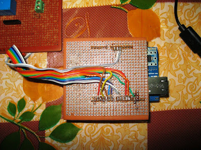
You can also make your own protoshield which can easily fit on top Arduino like this:


Once you finish soldering stuff, now you are ready for your main code upload.


STEP 4:

Uploading Arduino AutoHome code to the Board:

Here is the Arduino AutoHome code just copy and paste it into your Arduino IDE sketch.

123456789101112131415161718192021222324252627282930313233343536373839404142434445464748495051525354555657585960616263646566676869707172737475767778798081828384858687888990919293949596979899100101102103104105106107108109110111112113114115116117118119120121122123124125126127128129130131132133134135136137138139140141142143144145146147148149150151152153154155156157158159160161162163164165166167168169170171172173174175176177178179180181182183184185186187188189190191192193194195196197198199200201202203204205206207208209210211212213214215216217218219220221222223224225226227228229230231232233234235236237238239240241242243244245246247248249250251252253254255256257258259260261262263264265266267268269270271272273274275276277278279280281282283284285286287288289290291292293294295296297298299
//for use with IDE 1.0
//open serial monitor to see what the arduino receives
//use the \ slash to escape the " in the html
//for use with W5100 based ethernet shields
// this project is hosted at
// http://code.google.com/p/arduino-autohome/
#include <SPI.h>
#include <Ethernet.h>
byte mac[] = { 0x90, 0xA2, 0xDA, 0x0D, 0x78, 0xE0 }; // <------- PUT YOUR MAC Address Here
byte ip[] = { 192, 168, 1, 102 }; // <------- PUT YOUR IP Address Here
byte gateway[] = { 192, 168, 1, 254 }; // <------- PUT YOUR ROUTERS IP Address to which your shield is connected Here
byte subnet[] = { 255, 255, 255, 0 }; // <------- It will be as it is in most of the cases
EthernetServer server(80); // <------- It's Defaulf Server Port for Ethernet Shield
String readString;
//////////////////////
void setup()
{
  pinMode(6, OUTPUT); // Pin Assignment through which relay will be controlled
  pinMode(7, OUTPUT);
  pinMode(8, OUTPUT);
  pinMode(9, OUTPUT);
  
  
  //start Ethernet
  
  Ethernet.begin(mac, ip, gateway, subnet);
  server.begin();
  
  //enable serial data print
  
  Serial.begin(9600);
  Serial.println("server LED test 1.0"); // so that we can know what is getting loaded
}
void loop()
{
   
  
  // Create a client connection
  EthernetClient client = server.available();
  if (client) {
    while (client.connected()) {
      if (client.available()) {
        char c = client.read();
        
        //read char by char HTTP request
        if (readString.length() < 100) {
          //store characters to string
          readString += c;
          //Serial.print(c);
        }
        //if HTTP request has ended
        if (c == '\n') {
          ///////////////
          Serial.println(readString); //print to serial monitor for debuging
          /* Start OF HTML Section. Here Keep everything as it is unless you understands its working */
          
          client.println("HTTP/1.1 200 OK"); //send new page
          client.println("Content-Type: text/html");
          client.println();
          //client.println("<meta http-equiv=\"refresh\" content=\"5\">");
          client.println("<HTML>");
          client.println("<HEAD>");
          client.println("<meta name='apple-mobile-web-app-capable' content='yes' />");
          client.println("<meta name='apple-mobile-web-app-status-bar-style' content='black-translucent' />");
          client.println("<link rel=\"stylesheet\" type=\"text/css\" href=\"http://arduino-autohome.googlecode.com/svn/trunk/autohome.css\" />");
          
          
          client.println("</HEAD>");
          client.println("<body bgcolor=\"#D0D0D0\">");
          
          client.println("<hr/>");
          client.println("<hr/>");
          client.println("<h4><center><img border=\"2\" src=\"https://blogger.googleusercontent.com/img/b/R29vZ2xl/AVvXsEh7D936U9HueV3OmYSI_yfSMGiFYI9L5gDeW2ydPt9eTugpNaUxyr_ABI4QjhPSRt3bhA4v_eLg3GYq133qd9QDqu5v7x9OwdsDSfQZyy2fc9bWrEneR1WpAN7LWgdTfMOpehMpzShvW7U/s960/Logo.jpg\" /></center></h4>");
          client.println("<hr/>");
          client.println("<hr/>");
          
          client.println("<br />");
          client.println("<br />");
          client.println("<br />");
          client.println("<br />");
          client.println("<br />");
         
         // Relay Control Code
          client.println("<a href=\"/?relay1on\"\">Turn On Light 1</a>");
          client.println("<a href=\"/?relay1off\"\">Turn Off Light 1</a><br />");
          
          client.println("<br />");
          client.println("<br />");
          client.println("<br />");
          client.println("<br />");
          
          client.println("<a href=\"/?relay2on\"\">Turn On Light 2</a>");
          client.println("<a href=\"/?relay2off\"\">Turn Off Light 2</a><br />");
          
          client.println("<br />");
          client.println("<br />");
          client.println("<br />");
          client.println("<br />");
          
          client.println("<a href=\"/?relay3on\"\">Turn On Light 3</a>");
          client.println("<a href=\"/?relay3off\"\">Turn Off Light 3</a><br />");
          
          client.println("<br />");
          client.println("<br />");
          client.println("<br />");
          client.println("<br />");
          
          client.println("<a href=\"/?relay4on\"\">Turn On Light 4</a>");
          client.println("<a href=\"/?relay4off\"\">Turn Off Light 4</a><br />");
          client.println("<br />");
          client.println("<br />");


            // control arduino pin via ethernet Start //
          
          
          if(readString.indexOf("?relay1on") >0)//checks for on
          {
            digitalWrite(6, HIGH); // set pin 4 high
            Serial.println("Led On");
            client.println("<link rel='apple-touch-icon' href='http://chriscosma.co.cc/on.png' />");
            //client.println("Light 1 Is On");
            client.println("<br />");
        }
          else{
          if(readString.indexOf("?relay1off") >0)//checks for off
          {
            digitalWrite(6, LOW); // set pin 4 low
            Serial.println("Led Off");
            client.println("<link rel='apple-touch-icon' href='http://chriscosma.co.cc/off.png' />");
            //client.println("Light 1 Is Off");
            client.println("<br />");
        }
          }
          
          if(readString.indexOf("?relay2on") >0)//checks for on
          {
            digitalWrite(7, HIGH); // set pin 4 high
            Serial.println("Led On");
            client.println("<link rel='apple-touch-icon' href='http://chriscosma.co.cc/on.png' />");
            //client.println("Light 2 Is On");
            client.println("<br />");
          }
          else{
          if(readString.indexOf("?relay2off") >0)//checks for off
          {
            digitalWrite(7, LOW); // set pin 4 low
            Serial.println("Led Off");
            client.println("<link rel='apple-touch-icon' href='http://chriscosma.co.cc/off.png' />");
            //client.println("Light 2 Is Off");
            client.println("<br />");
          }
          }
          
           if(readString.indexOf("?relay3on") >0)//checks for on
          {
            digitalWrite(8, HIGH); // set pin 4 high
            Serial.println("Led On");
            client.println("<link rel='apple-touch-icon' href='http://chriscosma.co.cc/on.png' />");
           // client.println("Light 3 Is On");
            client.println("<br />");
          }
          else{
          if(readString.indexOf("?relay3off") >0)//checks for off
          {
            digitalWrite(8, LOW); // set pin 4 low
            Serial.println("Led Off");
            client.println("<link rel='apple-touch-icon' href='http://chriscosma.co.cc/off.png' />");
            //client.println("Light 3 Is Off");
            client.println("<br />");
          }
          }
          
          
           if(readString.indexOf("?relay4on") >0)//checks for on
          {
            digitalWrite(9, HIGH); // set pin 4 high
            Serial.println("Led On");
            client.println("<link rel='apple-touch-icon' href='http://chriscosma.co.cc/on.png' />");
            //client.println("Light 4 Is On");
            client.println("<br />");
          }
          else{
          if(readString.indexOf("?relay4off") >0)//checks for off
          {
            digitalWrite(9, LOW); // set pin 4 low
            Serial.println("Led Off");
            client.println("<link rel='apple-touch-icon' href='http://chriscosma.co.cc/off.png' />");
            //client.println("Light 4 Is Off");
            client.println("<br />");
          }
          }
          
         // control arduino pin via ethernet End //


          // Relay Status Display
          client.println("<center>");
          client.println("<table border=\"5\">");
          client.println("<tr>");
          
          if (digitalRead(6))
          {
           client.print("<td>Light 1 is ON</td>");
           
          }
          else
          {
            client.print("<td>Light 1 is OFF</td>");
           
          }
          
          
          client.println("<br />");
          
          if (digitalRead(7))
          {
           client.print("<td>Light 2 is ON</td>");
           
          }
          else
          {
            client.print("<td>Light 2 is OFF</td>");
            
          }
          
          client.println("</tr>");
          client.println("<tr>");
          
          if (digitalRead(8))
          {
           client.print("<td>Light 3 is ON</td>");
           
          }
          else
          {
            client.print("<td>Light 3 is OFF</td>");
            
          }


          if (digitalRead(9))
          {
           client.print("<td>Light 4 is ON</td>");
          
          }
          else
          {
            client.print("<td>Light 4 is OFF</td>");
           
          }
          
          client.println("</tr>");
          client.println("</table>");
          
          client.println("</center>");


          //clearing string for next read
          
          readString="";
          client.println("</body>");
          client.println("</HTML>");
          delay(1);
          //stopping client
          client.stop();
        }
      }
    }
  }
}


Upload this code to your UNO board. Now you are ready to your your Automation Project, just plug your Ethernet shield to router and and you will be able to find the control page on the IP Address specified by in in the Arduino Code. So directly enter the  IP address in the web browser of the the device which is on the same network as that of your Arduino.

So you will have the control page as shown below:


As you understand the code you can modify to your need.
So enjoy controlling things wirelessly..