 |
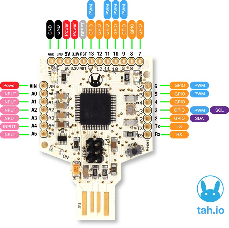
| TAH Main Board |
In this blog post I am going to introduce the Tah platform and talk about some of the applications using it.
Tah is a hardware as well as a software platform. The hardware has following characteristics
- An Arduino with Bluetooth Low Energy (BLE)
- Onboard USB (HID device) - emulating a keyboard and a mouse
- Great building block (like a LEGO) for your home automation systems using Arduino.
USB HID-Compatible
 ATmega32u4 — the microcontroller at the heart of Tah — has onboard USB 2.0 support, that is used to directly program the Tah without having to use a USB-to-Serial converter. Tah can also act as a USB human interface device (HID), which enables you to create your own keyboard, mouse, joystick, or other input devices, all without the need for installing special software on the host computer. If you want to create a new smarter custom keyboard that communicates with your smartphone, you need not look beyond the Tah. It already has sample applications that allow you to control your PC, Mac, Linux, PlayStation and Xbox without ever needing to write any code for those platforms — all you need to do is program your Tah board and make a smartphone app, for which we’ve also provided open source examples for both iOS and Android to get you started.
Bluetooth Beacon
 Each Tah board can serve as a Bluetooth beacon which tells your smartphone where exactly it is located based on the beacon’s unique identifier. This is amazing for indoor navigation, contextual notifications, and microlocalization.
Here are some of the interesting applications that can be built using the Tah and its shields.
Infrared Control (IR Transceiver Shield)
IR has been used for near range wireless communication for a long time. We have TVs, music systems, air conditioners and so many other things that have their own remote control
We have created an IR shield which has a transmitter as well as a receiver on board. With this connected to your Tah, you have a universal remote that can be controlled from your smartphone. Forget keeping a bunch of remotes to control everything in your living room. You could do all of that from a single app on your phone.
Relays (Relays + Sensors Shield)
Electronics is usually associated with low voltage DC appliances but so much of what we use everyday runs on 110V/220V AC. All our light bulbs, fans and everything else.
To control these there is a Relay shield that translates signals between DC and AC so to speak. One can use the GPIO pins 2 and 3 from the Tah to control 2 relays.
Bridge the gap between electronics and electrical with this relay plus sensor shield. It comes with its own app which you can use with some standard sensors such as the depth and temperature sensors among others.
- Input working voltage: 7V to 12V DC
- Two Relays rated 5V DC.
- Load Capacity: 10A/120VAC, 10A/24VDC, 7A/250VAC
- Relays are connected to Pin number 2 and 3 of Tah
- Digital Pin Numbers 4 to 13 & Analog Pin Numbers A0 to A5 all are connected to 3 pin standard Grove connector
Arduino
That's why we have the Shield Shield which consists of the Arduino UNO R3 layout which let's you use the already available shields in their projects. This shield makes Tah compatible with all existing Arduino Shields, It means all your Arduino-compatible shields are also compatible with the Tah. (Input working voltage: 7V to 12V DC)
---
By no means is the above list comprehensive. There are many more amazing things that can be built using the Tah.
Examples on the website. A forum to discuss more about this.
If you would like this device, you can grab them here.
(This is a product of Reavealing Hour Creations who run this blog and the IOT Community)


